Add Hand Rail ( Modeling > press F2 > Misc Steel > " Hand Rail ")

Tool summary :

Also see :

page 1 | contents | F2 > miscellaneous steel > hand rail | edit window | top


   Adding a handrail along the gage line of a stair (an example) :

You can add handrail with connections to wide flange or channel beams or -- as shown in this example -- to channel stairs. ' Welded ' (' Plain End ') or ' Continuous Bottom Plate ' handrail can be used for other material types or to add handrail that does not connect to anything.

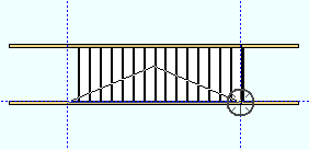
Note: To generate a construction line along the gage line of a channel stair stringer, select the stair stringer material, then Construction Line Add Material . Be sure to select the material, not the member; to do this, you need to set the selection filter to ' Material ' or use " Select Other " on the context menu . The construction line that Construction Line Add To Material generates along the channel's gage line is a white construction line. In the following example (step 1), this construction line has been turned to blue so that you can see it better.

1 . Invoke Section View and locate two points along the gage line of the channel stair stringer to obtain the section view shown in step 2, whose work plane includes those two points.
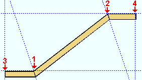
2 . Add construction lines for work point location. Invoke Add Hand Rail . Locate the main section work points ( 1 and 2 ). Then locate the work points for the left return ( 3 ) and right return ( 4 ).
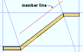
3 . Make entries to the Hand Rail window, then press " OK ." The handrail's member line is placed above the main section, per the settings for " Member line " " Finished floor distance " and " Floor thickness ." Right-click ( Return ) unless you want to add another hand rail.
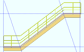
4 . If User and Site Options > Modeling > " Automatically process after modeling operation " is set to ' Process and create solids , ' the new handrail will have automatically undergone all phases of Process and Create Solids . You can now display the handrail in a solid form .

page 1 | contents | F2 > miscellaneous steel > hand rail | edit window | top


   Step-by-step instructions :

1 . Before adding the hand rail:

2 . Invoke Hand Rail using any one (1) of the following methods:

Hand Rail

Methods 1, 2 & 3 : A Hand Rail icon can be added to your toolbar (classic) or ribbon (lightning). The icon, keyboard shortcut or context menu command can be found in the group named ' Model -- Member '. For lightning, Customize Interface is used to configure ribbons, keyboards, the context menu and modes.

Method 4 : Press F2 > check the box for " Misc Steel " > double-click " Hand Rail ."

3 . Locate- Pan -Return mouse bindings become active so that you can locate the work points of the handrail member. Locating work points for returns (steps 3c & 3d) is optional . Also , you may get a Repeat mouse binding instead of Pan -- see this note .

bindings

3a : The status line prompts, " Locate TOS for Left End ." Move your mouse pointer ( ) to place the point location target ( ) where you want the left end of the main section, then left-click ( Locate ).

3b : The status line prompts, " Locate TOS for Right End ." Move your mouse pointer ( ) to place the point location target ( ) where you want the right end of the main section, then left-click ( Locate ).

3c : The status line prompts, " Locate TOS for Left Return End ."

Alternative 1 : Move your mouse pointer ( ) to place the point location target ( ) where you want the left end of the left return, then left-click ( Locate ).

Alternative 2 : Right-click ( Return ) if you don't want a left-end return.

3d : The status line prompts, " Locate TOS for Right Return End ."

Alternative 1 : Move your mouse pointer ( ) to place the point location target ( ) where you want the right end of the right return, then left-click ( Locate ).

Alternative 2 : Right-click ( Return ) if you don't want a right-end return.

4 . The Hand Rail window opens. Click here for a discussion of some of the key settings on this window.

Alternative 1 : Press " OK " to close the Hand Rail window and save the changes you have made to it. Go to step 5.

Alternative 2 : Press " Cancel " to close the Hand Rail window and end the Add Hand Rail operation. Do not continue.

5 . Locate - Repeat - Return mouse bindings become active.

bindings

Alternative 1 : Right-click ( Return ) if you are done adding handrail.

Alternative 2 : Add another handrail by following these instruction beginning with step 3 .

Alternative 3 : Place your mouse pointer ( ) and middle-click ( Repeat ) to lay out a handrail just like the own you just added. The handrail will be placed beginning at the point where the point location target ( ) is at.

Note: A Repeat mouse binding may also appear in step 3 , at the beginning of the Add Hand Rail operation, if you have edited (or added) a handrail and pressed " OK " on its edit window during your current Modeling session, Repeat generates an exact duplicate of the last-generated handrail, without your having to locate a second point or make entries to the Hand Rail edit window.

6 . What you need to do next depends on the choice made to User and Site Options > Modeling > " Automatically process after modeling operation ."

Possibility 1 : If " Automatically process ... " is ' Process and create solids ', then Process and Create Solids of the newly added handrail will take place automatically. You don't need to do anything more to get the results that are discussed in step 7.

Possibility 2 : If " Automatically process ... " is ' Process ' or ' Do nothing ', the new handrail will be marked for processing and can only be displayed in stick form . You need to Process > Process and Create Solids before you can get many of the results that are discussed in step 7.

7 . Following are some of the results you get after adding a handrail:

Since Process and Create Solids will have been done automatically or manually in step 6, you can display the handrail in one of the three solid forms or use Detail Members to generate a shop drawing of the handrail.

Also as a result of step 6, connections to the supporting members are generated, as are the various component material types that make up the handrail.

page 1 | contents | F2 > miscellaneous steel > hand rail | edit window | top


   Handrail material types :

Before adding a handrail, you should be aware of what material types are available for you to use. This is especially true if you are adding a handrail with angle posts and rails as opposed to pipe or tube posts and rails -- for reasons described here .

Material Type Used For
HSS round (pipe) posts , pickets , top rails , midrails , grab bars , splice connections for pipe/tube top rails , splice connections for pipe/tube midrails , splice connections for grab bars , P-end top rail corner elbows , P-end midrail corner elbows .
HSS rectangular (tube) posts , pickets , top rails , midrails , grab bars
angle posts , top rails , midrails , stabilizers for toe plates , clip angle post connections .
flat bar top rails , midrails , mesh frames
grating tread wire mesh
round bar picketssplice connections for pipe/tube top rails , splice connections for pipe/tube midrails , splice connections for grab bars , supports for grab bars
square bar pickets
rectangular plate   toe plates , toe plate splice plates , closure plates on tube posts , base plate post connections , continuous bottom plate post connections , rectangular plate post connections , support plate & "tab" on shear tab (pipe/tube) post connections , "tab" on shear tab (angle) post connections ,
round plates closure plates on pipe posts  
  bent plate bent plate post connections
bent plate layout bent plate mesh frames
flat plate layout plate for detail wire outline
  W tee W tee post connections

page 1 | contents | F2 > miscellaneous steel > hand rail | edit window | top


   Decide the connection type before adding work points :

The connection type that is to be used to connect the handrail to a support, as well as the materials used, determine how you should locate points when adding the handrail.

To Model handrail in Space ( or to any material )
Connection Comments
  Welded
(Plain End)
These connection types work well for any type of material since they do not provide true connectivity. For example, use them for a stair with a tube stringer or on a beam of any type of material. ' Welded ' can be used for a top flange or web connection. ' Continuous Bottom Plate ' is strictly for a top flange.
  Continuous Bottom Plate


To Top Flange of Channel or Wide Flange ( beam or stair )
Connection Comments  
Base Plate   You need to be in the plane of the top flange when adding work points for a handrail with these types of connections. If your current view is not already in that plane, Surface to go to the plane, even if the support is sloping. Or you can cut a section view . Use Construction Line Add Material to get a white construction line along the gage line of a channel, or the gage lines of a wide flange.
Continuous Bottom Plate
Welded
(Plain End)


Web Connections to the back of a Channel Beam
( the beam's workline is the back of the channel )
Connection Comments
Bolted (Angle) Place your work points at the channel beam's top flange elevation. The Add Handrail program automatically extends the handrail posts below the top flange when you apply these connections. For ' Bolted (Angle) ' you need to offset the work points in toward the beam workline by the thickness of the angle top rail in order to get the posts flush with the back of the channel. For ' Rectangular Plate ', offset the work points away from the beam by half the pipe or tube post depth plus the thickness of the rectangular plate.
  Rectangular Plate
Welded
(Plain End)
Place your work points the distance you want the posts to extend below the top flange of the channel beam. For pipe or tube hand rail, offset the work points away from the beam by half the depth of the pipe or tube posts. For angle handrail, offset the work points in toward the beam by the thickness of the angle top rail.


Web Connections to a Wide Flange or Channel Beam or a Channel Stair Stringer
Connection Comments
Bent Plate Place your work points at the beam's top flange elevation. The program automatically extends the handrail posts below the top flange when you apply these connections. Work points need to be offset away from the top flange so that the post clears the flange with, for example, a 1/4 inch clearance. For a ' PIPE 1 1/2 STD ' post " Section size ," this means you would need to offset the hand rail by half the post " Depth " (1.9/2 = .95 inch) then add a 1/4 inch for a total clearance of 1.2 inch. All of these connections except the one marked "(Angle)" would work for this example.
Clip angle
Rectangular Plate
Shear Tab
Shear Tab (Angle)
W Tee

page 1 | contents | F2 > miscellaneous steel > hand rail | edit window | top


   Add construction lines for locating handrail work points :

The INCL points 1 , 2 , 3 , 4 are positioned to add a handrail whose posts clear the beam top flanges for web connections . 1 & 2 are the left & right work points of the main section . 3 & 4 are work points for the left & right returns .

  • Before placing the construction lines that you want for work point location, you need to be in a view whose work plane includes all the points that you want to locate. For adding hand rail to non-sloping beams, such as in the example immediately above, this would be a plan view at the elevation of the top flanges of those beams. For adding handrail to the top flange of a sloping beam, Surface the top flange of that beam to get in the proper plane. For adding a handrail to a stair, the example at the top of this page shows the use of Section View to cut a view in the proper plane.
  • Place construction lines for locating the left end of the main section and the right end of the main section. These work points center the end posts if the " Type " of posts is ' Pipe ' or ' Tube '. If the " Type " of posts is ' Angle ', the end posts are inside the work points. Click here for a picture.
  • Since returns are optional , you only have to place construction lines for those returns that you want.
  • If you are placing intermediate posts with ' User ' as the " Post spacing method ," you need to place construction lines where you want the posts. This is not necessary if you plan to use any other " Post spacing method '.
  • Take into consideration the " Type " of post connection that you plan to use. For posts that connect to the top flange , you will want to place construction lines on the top flange, probably on the gage line. For posts to the back of a channel and web connections , you will want to offset a construction line away from the supporting member.

page 1 | contents | F2 > miscellaneous steel > hand rail | edit window | top


   Work points (the top of steel workline) aligns posts and rails :

As mentioned above , the work points for an angle handrail position the handrail in a different way than they do for a pipe or tube handrails. Also take into consideration the connection type when determining where to locate work points.

Posts, Rails and Work Points
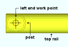
pipe (shown) or tube
angle
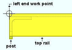
  • The first two work points that you locate when adding a handrail position the first and last posts of the main section (assuming the " Condition " is ' Post '). ' Pipe ' or ' Tube ' end posts are centered on these work points. ' Angle ' end posts are "inside" the work points.
  • The heel of a " Top rail " that is set to ' Angle ' aligns with the workline, and the angle midrails align with that top rail. Angle posts are offset from the workline by the thickness of the angle top rail.

page 1 | contents | F2 > miscellaneous steel > hand rail | edit window | top


   Returns are optional :

page 1 | contents | F2 > miscellaneous steel > hand rail | edit window | top


   The Hand Rail window :

For a handrail that connects to one or more supporting members, the work points that you locate should be at the top of steel (TOS) of the supporting members. The Hand Rail window positions where rails are placed above these work points and how posts are placed between these work points.
  • Handrail post " Types " can be ' Angle ' or ' Pipe ' or ' Tube '. Top rails and mid rails can be ' Angle ' or ' Flat bar ' or ' Pipe ' or ' Tube '. Pickets are also available. A toe plate (rectangular plate) and grab bar (pipe) are optional.
  • The placement of many hand rail components is defined by setting the " Finished floor distance " ( actual or vertical ) which that component is above the " Floor thickness ." The top rail " Reference line " sets the member line.
  • Setting the " Walk side " positions the grab bar and toe plate. For angle handrails (but not pipe and tube handrails), it orients the angle posts and angle rails so that they point toward or away from the work line .
  • A handrail post connection " Type " is not a system connection . You need to specify the section sizes, material dimensions and hole patterns yourself. Welds can be applied to the member detail using Weld Add .
  • As described in this warning , you should edit the Hand Rail window instead of editing individual materials. Do final cleanup of the handrail using Model > Material tools after you are done editing the handrail member for the last time.

page 1 | contents | F2 > miscellaneous steel > hand rail | edit window | top